Valve Timing Diagram Of Ic Engine
The graphical diagrams are known as valve timing diagram in automobile engineering. A valve timing diagram is a graphical representation of the opening and closing of the intake and exhaust valve of the engine, the opening and closing of the valves of the engine depend upon the movement of piston from tdc to bdc, this relation between piston and valves is controlled by setting a graphical representation between these two, which is known as valve timing diagram.
How To Draw Valve Timing Diagram Youtube inside Ic

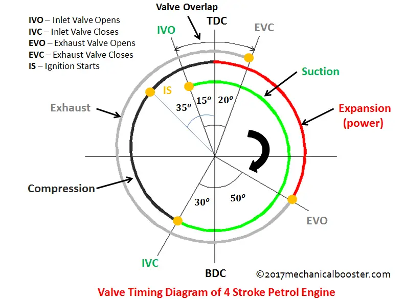
Explanation • iv opens 20˚ before tdc.

Valve timing diagram of ic engine. Engine valve timing is most critical process of ic engines. This relation between the valve opening timings to the piston moves from the top dead centre (tdc) to the bottom dead centre (bdc) can be represented on a circle. Valve overlap with traditional fixed valve timing, an engine will have a period of valve overlap at the end of the exhaust stroke, when both the intake and exhaust valves are open.
The valve timing diagram is basically a figure that shows the valve opening and closing of many valves of the engine. The timing of opening & closing of valves is specified in degrees corresponding to the position of engine's pistons. This is called the valve timing diagram.
Last part of unit 1 page 2 of 13 prof. The valve timing is one of the important factors that affect the volumetric efficiency of the engine. Calculate the ip,bp, brake thermal efficiency.
Valve timing is the regulation put on the engine valves, how they set to open and close during working cycle. As we know engines at higher speeds cannot operate as we speak theoretically, so at higher speeds some valve must be opened earlier and some later and same in the case of the closing of valves. Calculate & compare the performance characteristics.
The exact moment at which the inlet and outlet valve opens and closes with reference to the position of piston and crank shown diagrammatically is known as valve timing diagram. Engine valve timing is the most critical process of ic engines. However, in a practical situation, opening and closing of engine valve occur at some degree (time) before or after tdc and bdc.
Valve timing diagram for si engine valve timing diagram for ci engine. Valve timing diagram of four stroke engine / otto within valve. • iv closes 35۫ after bdc to takethe advantage of momentum of rapidly moving gases (ram effect).
The inlet valve usually opens few degrees before the piston reaches tdc in its exhaust stroke. Figure 1.73 shows actual valve timing diagram for four stroke si engine. The intake valve is opened before the exhaust gases have completely left the cylinder, and their considerable velocity assists in drawing in the fresh charge.
The timing is expressed in terms of degrees of crank rotation. The timing of the opening & closing of valves is specified in degrees corresponding to the position of engine’s pistons. Determine the valve timing diagram of si engine & ci engine.
Analyze the influence of variations in tdc and bdc operations 3. Jilani effect of valve timing diagram on volumetric efficiency: In the petrol engine, various strokes are performed to obtain the results from an engine.
Internal combustion engine has always been interesting with respect to optimization techniques; The diagram shows the timing of opening and closing of intake and exhaust valve during one complete cycle of four strokes. ( port timing diagram for ci.
By denoting the corresponding position of the piston attached to the crankshaft at which these strokes occurs, you can draw the exact moment in the sequence of events at which the. A valve timing diagram is a graphical representation of the opening and closing of the intake and exhaust valve of the engine, the opening and closing of the valves of the engine depend upon the movement of piston from tdc to bdc, this relation between piston and valves is controlled by setting a graphical representation between these two, which is known as valve timing diagram. Valve timing diagram (vtd) is no such exception.
The charge is compressed till the spark occurs. #gate #ese #isro #barc #engineerin. It requires a finite period of time for its operation so a time advance is given for proper functioning.
🔗valve timing diagram of four stroke si engine 🔗working of four stroke spark ignition engine with pv diagram valve lead in engine theoretically, the engine valve opens and closes at tdc (top dead center) and bdc (bottom dead centre). The valves cannot open and close abruptly; A valve timing diagram is a representation of the positions of the crank when the various operations as inlet valve opening, closing, exhaust valve opening and closing and also the beginning and end of various strokes.
The diesel engines are also known as compression ignition engines.
What is Valve Timing & How It Affects Engine Performance

VALVE TIMING DIAGRAM OF TWO STROKE AND FOUR STROKE ENGINES

What Is Engine Knock for Valve Timing Diagram Of Ic Engine

Marine Engines & Propulsion in Valve Timing Diagram Of Ic

Modeling The Effect Of Variable Timing Of The Exhaust

Pin on Diagram

Valve Timing Diagram of Two Stroke and Four Stroke Engine
Engine Valve Timing Diagram

Valve Timing Diagram Diesel Engine Pdf Mesin
Lead, Lag, and Overlap In the Valve Timing Diagram and

VALVE TIMING DIAGRAM OF TWO STROKE AND FOUR STROKE ENGINES
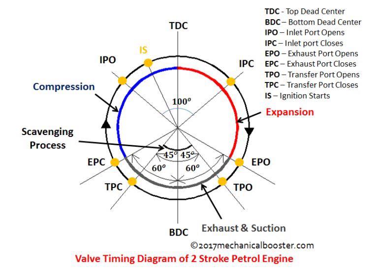
Image016 throughout Ic Engine Valve Timing Diagram

Diesel Engine Jasdeep Singh for Valve Timing Diagram Of

What Is The Significance Of Valve Timing Diagram ? How To

Valve Timing Diagram of Two Stroke and Four Stroke Engine
Valve Timing Diagram Valve Timing Diagram For Four

Valve Timing Diagram of Four Stroke SI Engine Low Speed

valve timing diagram of 2 stroke diesel engine

Valve timing diagram of 4 stroke IC Engine Explained in
