Boss Snow Plow Wiring Harness Diagram
Pin wire color function 1 red passenger side out. Each component should be set and connected with different parts in particular way.
Boss Snow Plow Wiring Diagram Boss Snow Plow Boss Snow Plow Wiring Diagram Motorcycle Review

It will fit v straight blade plows with a 13 pin plow side harness.

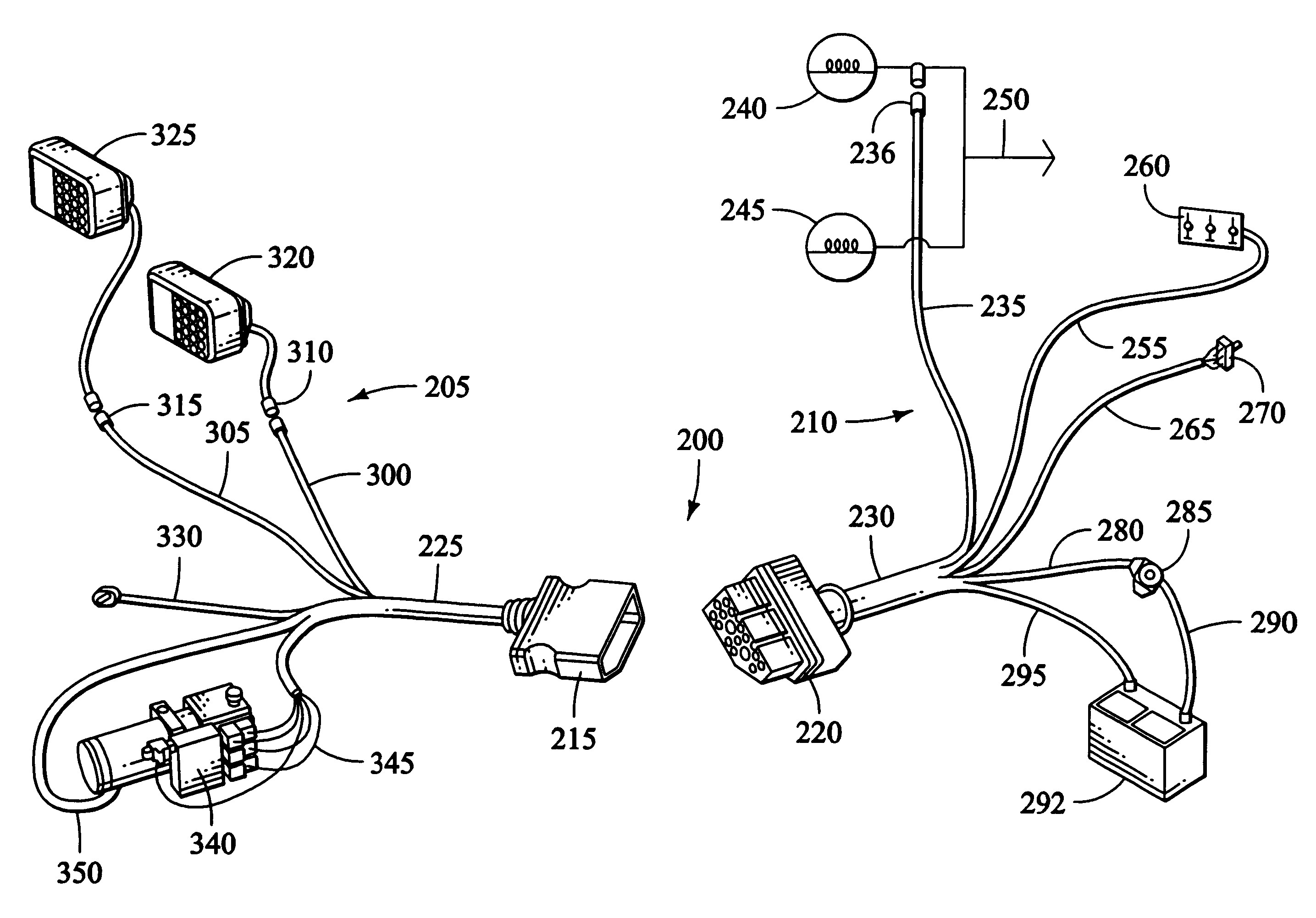
Boss snow plow wiring harness diagram. For safety the boss includes cross over pressure relief to prevent damage by overstress. Vehicles equipped with air bags are designed such that the air bags will be activated in a frontal collision equivalent to hitting a solid barrier (such as a wall) at approximately 14 mph or more, or, Wiring harness (93) into the back of the passenger side vehicle headlight.
Collection of boss v plow wiring diagram. Begin the assembly procedure by cutting down each corner of the plow box so that each wall of Secure wiring harness (61) to light bar (13) as shown above.
Mt n united states formno. Boss v plow solenoid wiring diagram. The plow is mounted on the vehicle.
Boss control harness repair kit 13 pin diagram plow rt2 wiring rt1 v blade the largest rt3 tripedge snowplow wing not functioning side 11pin to 13pin western vehicle 3 1hhc curtis handheld sno light snow 5 relay lights won t turn off straight installation manual pro power and xt diagrams for old wide out joystick 9. Insert the unconnected ends of the plow wiring harness into the back of the coupler through the rubber grommet. This manual is used for the assembly of all standard, super, and heavy duty boss straight blade plows.
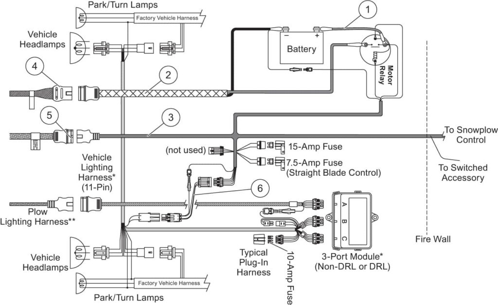
Boss part msc08001 2008 up vehicle side wiring harness 13 pin is used on all boss full sized truck plows. The boss snow plow wiring diagram simple wiring diagram for boss snow plow boss plow wiring diagram v boss v plow wire harness installation boss snow plow wiring harness. All vehicles and headlight adapters may not be
The boss snow plow wiring diagram western plow wiring diagram best arctic snow plow wiring diagram for saber 1 with. The boss snowplow has been carefully designed and built for years of carefree performance. Rt3 wiring diagram rt3 wiring diagram.
It consists of instructions and diagrams for different varieties of wiring methods along with other items like lights, windows, and so forth. 8 gray plow low beam. Secure wiring harness g10126 33.
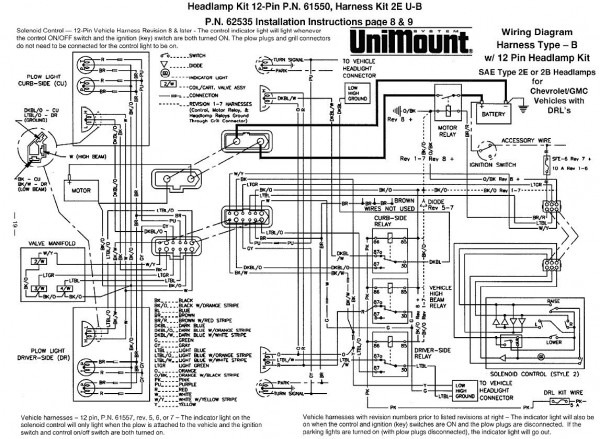
Just click on the part number or truck type year vehicle you need to view the boss snow. Electrical system wiring schematic (truck side) electrical system wiring schematic (truck side) g10272. Electrical system wiring schematic (plow side) g10271.
Wiring schematic wiring schematic g10004. 6 red / black driver side in. 2 green passenger side in.
7 gray / black plow high beam. 9 n / a n / a. Secure wiring harness g10126 32.
Boss 11 pin / 13 pin vehicle headlight adapter chart. Secure wiring harness (61) to light bar (13) using wire ties as shown above. 5 blue driver side out.
6 red black driver side in. With its simple attaching system, the boss can be attached or removed in seconds. See also ge refrigerator wiring diagram sample.
This is a general diagram for the universal headlight harness (reference nge headlight harness chart). 6 red black driver side in. 19 & newer 1/2 ton.
Part numbers and illustrations may vary. 8 27 2004 9 59 47 pm. Just click on the part number or truck type/year (vehicle) you need to view the boss snow plow part details and to return back to this part diagram page use your back browser button.
Take a look at the wiring diagrams on the boss site under manuals and look at the 11 and 13 pin configuration and you can see the differences. Boss 11 pin wiring harness diagram. A wiring diagram is a simplified standard photographic depiction of an electrical circuit.
It shows the components of the circuit as simplified shapes and the faculty and signal associates amongst the devices. If not, the arrangement won’t work as it ought to be. Recommended vehicle models refer to the boss snowplow application chart and selection guide.
Connect the plow side wiring harness to the hydraulic valve manifold as shown in figure 26. Recommended vehicle models refer to the boss snowplow application chart and selection guide. It consists of instructions and diagrams for different varieties of wiring methods along with other items like lights, windows, and so forth.
Each part should be set and connected with different parts in particular manner. Pin # wire color function 1 red passenger side out. If not, the structure will not work as it should be.
Snowplow assembly procedure 4 snowplow assembly procedure note: Fisher plow wiring diagram minute mount 2. Recommended vehicle models refer to the boss snowplow application chart and selection guide.
Boss Snow Plow Wiring Diagram Cadician's Blog
Wiring Diagram For A Boss Snow Plow boss 13 pin wiring harness diagram western snow plow parts

19 Elegant Western Snow Plow Wiring Harness Diagram

Boss V Plow Wiring Diagram For 2016 Gmc Truck Wiring Library
Boss Plow Wiring Harness Installation Wiring Diagram and Schematic
Boss Snow Plow Wiring Diagram Cadician's Blog
[DIAGRAM] Boss V Plow Wiring Harness Diagram FULL Version HD Quality Harness Diagram
Wiring Diagram For A Boss Snow Plow boss 13 pin wiring harness diagram western snow plow parts
Boss V Plow Wiring Diagram easywiring
Boss Snow Plow Wiring Harness
Boss Rt3 V Plow Wiring Diagram SHERRODSTAMPS
Snow Plow Wiring Harness Great Installation Of Wiring Diagram • Boss Snow Plow Wiring

Boss Snow Plow Wiring Harness

The Boss Snow Plow Wiring Diagram Gallery Wiring Diagram Sample

The Boss Snow Plow Wiring Diagram Gallery Wiring Diagram Sample
Boss Snow Plow Wiring Harness Diagram PATHETICMISERABLEPERSON

Boss Snow Plow 13 Pin Wiring Diagram Wiring Diagram and Schematic

20 Best Boss Snow Plow Wiring Diagram

Boss Plow Side Wiring Harness WIRGREM
